Page: 1
/ 14
Total 97 questions
AutoDesk Certified Professional in AutoCAD for Design and Drafting ACP-01101 Exam Questions
Question 1
A company's central server holds project directories that contain drawings. Team members who work onsite copy a directory locally to work offline.
Users often report that external references (xrefs) cannot be loaded after copying the project directories to their local machine from the company's central server.
How should you make sure that the users can load the xrefs without error?
Answer : A
the external references use relative pathsto load them without error after copying them locally from a central server. This way, you can avoid broken links due to changes in drive letters or folder names.
https://grabcad.com/tutorials/working-with-external-references-xrefs-autocad
Question 2
One of the lines in the drawing is at a 30 degree angle. What's the quickest way to align the X-axis of the UCS to that line?
Answer : A
UCS is a command that sets a new user coordinate system (UCS) by specifying points or by selecting an object. You can use the Object option to align the UCS with a selected object such as a line.
Based on3and4, UCSBASE is a system variable that sets the name of the current UCS base. PLINEGEN is a system variable that controls how linetype patterns are generated around vertices. LWEIGHT is a command that sets the current lineweight, which is used for new objects and affects objects in the current space only.
https://knowledge.autodesk.com/support/autocad/learn-explore/caas/CloudHelp/cloudhelp/2016/ENU/AutoCAD-Core/files/GUID-0BE49DA1-B323-4758-B49B-4C497D194C7A-htm.html
https://knowledge.autodesk.com/support/autocad/learn-explore/caas/CloudHelp/cloudhelp/2020/ENU/AutoCAD-Core/files/GUID-E658D5E7-EE5C-4A06-BF34-F71CDB363A71-htm.html
Question 3
Exhibit.
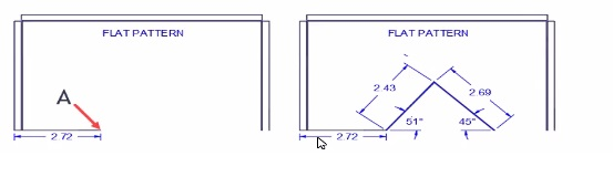
The exhibit on the right reflects a design change for the fiat pattern.
Starting at point A. while using dynamic input, which coordinates win draw both angered lines?
Answer : C
Dynamic input in AutoCAD allows you to enter coordinates and angles directly in the command line, providing real-time feedback on the drawing. To draw lines at specific angles and lengths, you use the format length Start Point (A): Begin drawing from point A. Enter Length and Angle: For the first line, input 2.43<51 to draw a line that is 2.43 units long at an angle of 51 degrees from the horizontal. Enter Length and Angle for Second Line: For the second line, input 2.69<-45 to draw a line that is 2.69 units long at an angle of -45 degrees from the horizontal. Using dynamic input in this manner ensures precise drawing and proper alignment as per the given angles and lengths.
Question 4
What should be typed at the command line in order to start creating a line for drawing reference that starts at a defined point and extends to infinity in the designated direction?
Answer : D
According to the AutoCAD for Design and Drafting documents1, the command that should be typed at the command line in order to start creating a line for drawing reference that starts at a defined point and extends to infinity in the designated direction isXLINE2.This command creates a construction line, which is a type of reference line that can help you manage accurate parameters of your drawing2.You can also use point objects as nodes or reference geometry for object snaps and relative offsets3.
Question 5
The Audit (AUDIT) command is used often on a project
How should the user interface be customized to display the Audit tool continuously? [Note Mac terminology appears in the parentheses 1
Answer : A
Open Customize User Interface (CUI): Type CUI in the command line and press Enter.
Locate the AUDIT Command: In the CUI dialog box, under the Customize tab, expand the Ribbon node and then expand the Panels node.
Add to Quick Access Toolbar: Drag the AUDIT command from the Panels list and drop it onto the Quick Access Toolbar in the Customize list.
Save Changes: Click Apply and OK to save the changes. The AUDIT tool will now be available in the Quick Access Toolbar for continuous display.
AutoCAD Help Documentation on Customizing the Quick Access Toolbar
Question 6
Exhibit.
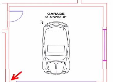
A CAD designer wants to use the clipboard method to copy the car block to a separate floor plan drawing, and the designer wants to make sure that it is pasted into the same position in the garage relative to the lower left-hand comer, as shown in the exhibit
Which clipboard workflow should the designer use?
Answer : D
Select the Car Block:
In the current drawing, select the car block.
Copy with Base Point:
Right-click and choose 'Clipboard' > 'Copy with Base Point'.
Specify the lower left-hand corner of the garage as the base point.
Switch to the Target Drawing:
Open the target drawing where you want to paste the car block.
Paste to Original Coordinates:
Right-click and choose 'Clipboard' > 'Paste to Original Coordinates'.
The car block will be pasted into the same position relative to the garage as in the original drawing.
AutoCAD User Guide on Clipboard Operations
Autodesk Knowledge Network: Copying and Pasting Objects in AutoCAD
Question 7
Refer to the exhibit.
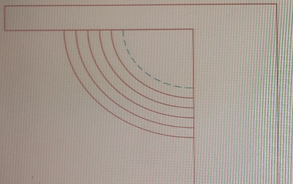
The exhibit shows a set of ornamental garden stairs going up to a walkway as part of a landscaping design.
You need to make sure that the edge of the top step in shown in a different linetype, as shown by the dashed line in the exhibit.
Which prompt in the OFFSET command should you use?
Answer : B
The Current prompt should be used to make sure that the edge of the top step is shown in a different linetype, as shown by the dashed line in the exhibit.This way, you can set a different linetype for your current layer before using the OFFSET command4.
https://knowledge.autodesk.com/support/autocad/learn-explore/caas/CloudHelp/cloudhelp/2021/ENU/AutoCAD-Core/files/GUID-C0E4246D-C420-42BD-A6FC-8B1852EFD005-htm.html