Page: 1
/ 14
Total 63 questions
AutoDesk Certified Professional in Revit for Electrical Design RVT_ELEC_01101 Exam Questions
Question 1
What should an electrical designer do to associate a lighting device with light fixtures in a model?
Answer : C
In Autodesk Revit Electrical Design, a lighting device (switch) must be associated with lighting fixtures through a switch system, not through electrical circuits. Switch systems are independent of lighting circuits and wiring, as they are intended to represent the control relationship between a light switch and the lighting fixtures it operates.
According to the Autodesk Revit MEP User's Guide (Chapter 17 -- Electrical Systems, pages 475--478), the official method is described under ''Creating a Switch System.''
''You can assign lighting fixtures to specific switches in a project. The switch system is independent of lighting circuits and wiring.'' (Revit MEP User's Guide, p. 475)
''To create a switch system:
Select one or more lighting fixtures in a view, and click Modify | Lighting Fixtures tab Create Systems panel Switch.
Click Switch Systems tab System Tools panel Edit Switch System.
Click Add to System, and select one or more lighting fixtures.
Click Select Switch, and select a switch in the drawing area.
Click Finish Editing System.''** (Revit MEP User's Guide, p. 476)
How It Works:
The switch system links a lighting device (switch) with lighting fixtures, enabling Revit to manage how light fixtures respond to specific switches.
Unlike electrical circuits, which define power flow and load connections to panels, the switch system defines control logic (which lights are turned on/off by which switch).
The designer begins by selecting the switch and then adding lights to its system, ensuring all lights associated with that switch are grouped correctly.
Supporting Extract from Revit Documentation:
''You can also create a lighting switch system by right-clicking the connector for a lighting fixture and clicking Create Switch System.'' (Revit MEP User's Guide, p. 475)
''Add lighting fixtures to the switch system... Click Select Switch and select a switch in the drawing area.'' (Revit MEP User's Guide, p. 476)
''The switch system is independent of lighting circuits and wiring.'' (Revit MEP User's Guide, p. 475)
Conclusion:
To associate a lighting device (switch) with light fixtures in a Revit electrical model, the designer must create a switch system. This is done by selecting the switch, then adding the desired lighting fixtures to that system using the Add to System and Select Switch tools under the Switch Systems tab.
Question 2
Which feature shows which user created 3n element?
Answer : B
In Autodesk Revit, the Worksharing Display Modes feature allows designers to visually inspect ownership and editing information about elements in a workshared model.
According to the Autodesk Revit MEP User Guide -- Chapter 54 ''Working in a Team'':
''Worksharing Display Modes can be used to visualize the ownership of elements, including which user created or modified them. For example, you can use the Worksharing Display command to show elements by their owner, workset, or checkout status.''
Thus, this mode identifies which user created or owns an element --- making B. Worksharing display modes the correct choice.
Other options:
A . Gray Inactive Worksets: Only shows non-active worksets in gray, not creator info.
C . Show History: Displays synchronization comments, not element ownership.
D . Worksets dialog: Shows ownership of worksets, not individual elements.
Question 3
Which Revit command is used to map a Keynote Table file?
Answer : D
The correct command in Revit used to map (assign or browse to) a Keynote Table file is Keynoting Settings.
In Revit, keynotes are driven by an external keynote table, typically a tab-delimited TXT file that must be assigned (mapped) in the project so keynote tags can read values correctly. The official Autodesk Revit MEP documentation clearly identifies that the Keynoting Settings dialog is where this mapping is performed.
From the documentation:
To access the Keynoting Settings dialog, the instructions state: ''click Annotate tab Tag panel drop-down (Keynoting Settings).''
Regarding keynote table file location mapping: ''Keynote Table --- Full Path displays the entire path of the keynote file... Saved Path displays the file name of the keynote file that is loaded.''
It goes further to explain file path types: ''Absolute identifies a specific folder... Relative finds the keynote file where the project file... is located... At Library Locations finds the keynote file where the stand-alone installation or network deployment specified.''
The command is explicitly referenced again when fixing a missing mapping: ''Unable to Load Keynote data. Check keynote table locations in Keynoting Settings.'' ''To specify the location of the keynote text file... click (Keynoting Settings).''
Other listed options do not perform keynote file mapping:
Keynote Manager does not exist as a command in native Revit.
Element Keynote is a tagging method.
Keynote Legend only displays already-mapped keynote information.
Question 4
Refer to exhibit.
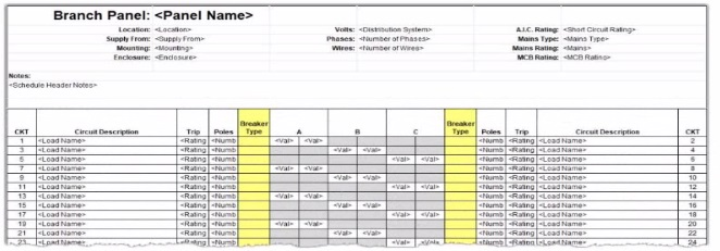
An electrical designer wants to report Breaker Type for each breaker in a panel schedule. The designer adds a column to the schedule as shown (and highlighted) in the image.
Which type of parameter should the designer create to add to the column?
Answer : C
In Autodesk Revit Electrical Design, panel schedules display data that originates from the Electrical Circuits category, not directly from the Electrical Equipment or Electrical Fixtures families. Each circuit in a panel schedule represents an instance of an Electrical Circuit object within Revit's system-based MEP structure. Therefore, to add an additional field like Breaker Type, the parameter must be created and assigned specifically to the Electrical Circuits category.
According to the Revit MEP User's Guide -- Chapter 50 ''Electrical Systems and Panel Schedules'':
''Panel schedules display parameters that are associated with electrical circuits, including load names, rating, poles, and breaker information. To include additional circuit information in a panel schedule, create a Project Parameter assigned to the Electrical Circuits category.''
This means the designer should: 1 Open Manage Project Parameters Add 2 Create a Project Parameter named Breaker Type 3 Assign it to the Electrical Circuits category 4 Set it to appear in schedules and tags, ensuring it becomes available for use in the panel schedule template
As noted in the Smithsonian Facilities Revit Template User's Guide:
''Custom circuit data fields such as 'Breaker Type' or 'Wire Tag' are defined as project parameters applied to the Electrical Circuits category so they can be displayed in panel schedule templates.''
Incorrect options:
A . Shared Parameter in Electrical Equipment --- Electrical Equipment holds overall panel data (e.g., Mains Rating, Voltage) but not per-circuit data.
B . Shared Parameter in Electrical Fixture families --- Fixtures are individual load devices, not part of the circuit's breaker assignment.
D . Project Parameter assigned to Electrical Equipment --- would apply to the panelboard as a whole, not to individual breakers in circuits.
Thus, the correct answer is C. Project Parameter assigned to Electrical Circuits, ensuring each breaker in the panel schedule can display its type individually and dynamically.
References:
Autodesk Revit MEP User's Guide -- Chapter 50 ''Electrical Systems and Panel Schedules,'' pp. 1134--1142
Smithsonian Facilities Revit Template User's Guide -- Section 8.7 ''Electrical Panel Schedule Customization,'' p. 91
Autodesk Revit Electrical Design Essentials -- ''Custom Circuit Parameters and Schedule Configuration''
Question 5
Refer to exhibit.
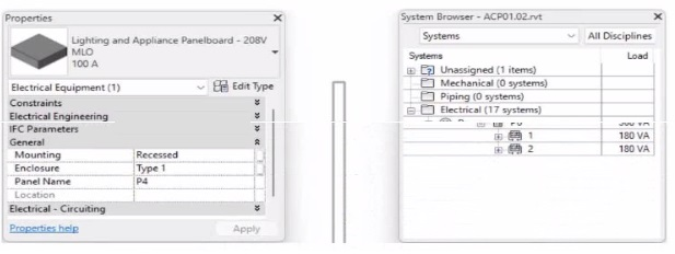
To which panel Is Panel P4 circuited?
Answer : B
In Autodesk Revit MEP Electrical Design, the System Browser is used to analyze and verify electrical systems, including panelboard connections, circuit hierarchies, and connected loads.
From the exhibit, the Properties palette shows that the selected equipment is a Lighting and Appliance Panelboard (208V MLO, 100A), named P4. To determine the parent panel that feeds Panel P4, we refer to the System Browser, which organizes the entire electrical distribution network hierarchically under the Electrical discipline.
In the System Browser on the right, under the Electrical category, we can observe that Panel P4 is nested directly under Panel P2. This organization indicates that P4 is circuited to (or fed from) Panel P2.
According to the Revit MEP 2011 User's Guide, Chapter 4, ''Electrical Systems---Using the System Browser,'' it states:
''The System Browser displays electrical systems in a tree structure. Each subpanel or device listed beneath a main panel is connected to that panel through an electrical circuit. When a panelboard appears under another, it indicates the subpanel is fed from that parent panel.''
This is further reinforced in Smithsonian Facilities Revit Electrical Template Documentation (April 2021), Section 8.3 ''Documentation Views,'' which describes:
''Panel schedules and browser hierarchies show the distribution sequence. Subpanels appear indented beneath their source panel, indicating electrical dependency and circuit assignment.''
Therefore, by interpreting both the Revit interface and Autodesk's documentation, Panel P4 is a subpanel connected to Panel P2, confirming that its electrical feed is assigned from Panel P2.
Final Verified Answer: B. Panel P2
Reference Sources:
Autodesk Revit MEP 2011 User's Guide, Chapter 4 --- Electrical Systems and the System Browser
Smithsonian Facilities Revit Template User's Guide, Section 8.3 --- Electrical and Fire Alarm Templates: Documentation Views
Question 6
Refer to exhibit.
(The Image is presented in Imperial units: 1 In = 25 mm [Metric units rounded).)
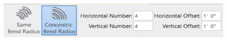
What is the electrical designer trying to do as shown in the exhibit?
Answer : B
The exhibit shown in the image is taken directly from the Revit MEP Electrical Systems workspace, specifically from the Parallel Conduits command interface. This dialog box appears when the designer activates the Place Parallel Conduits tool in the Systems tab Electrical panel Conduit dropdown Parallel Conduits.
In this interface, the designer can specify:
Horizontal Number / Offset -- defines how many conduits will be created horizontally and their spacing.
Vertical Number / Offset -- defines how many conduits will be created vertically and their spacing.
Bend Radius Options:
Same Bend Radius -- all conduits use identical bend radii.
Concentric Bend Radius -- conduits bend concentrically around a common center point.
According to Autodesk's Revit MEP 2011 User's Guide (Chapter 18, Electrical Systems -- Conduit Layout):
''The Parallel Conduits tool allows you to create multiple conduits side-by-side at the same time. You can specify the number of conduits horizontally and vertically, as well as the offset between them. You can also define whether bends have the same bend radius or concentric bend radii.'' --- Revit MEP User's Guide, Electrical Systems, Section: Conduit Layout
This tool is used when electrical designers need to route groups of conduits that run in parallel---such as power and data conduits running between panels or equipment racks. The Concentric Bend Radius option (as shown in the exhibit) ensures all conduit bends share a common center, which is critical for maintaining uniformity in conduit sweeps and avoiding clashes during coordination.
Therefore:
A . Add Cable Tray -- incorrect; the cable tray tool is separate and does not use bend radius options.
C . Array Conduit -- incorrect; arraying is a different geometric function not specific to conduit routing.
D . Place Multiple Pipe -- incorrect; applies to mechanical piping systems, not electrical conduits.
The display of Concentric Bend Radius, Horizontal Number, Vertical Number, and Offset confirms that the designer is using the Parallel Conduit placement tool.
Verified Reference Extracts from Revit Electrical Design Documentation:
Autodesk Revit MEP User's Guide (2011) -- Electrical Systems Conduit Layout ''Parallel Conduits Tool'' description.
Autodesk Revit MEP Training Curriculum -- Electrical Module, Exercise 6.3 ''Placing Parallel Conduits,'' which illustrates the same interface for bend radius configuration.
Question 7
An electrical designer has created a family and loaded It Into the project. The designer wants to connect the family to a power circuit but the Power icon is not available when the family Is selected.
How should the designer fix the problem?
Answer : D
In Revit Electrical Design, for a loadable family (such as electrical equipment, lighting fixtures, or devices) to connect to a power circuit, it must include an electrical connector defined in the Family Editor.
According to the Autodesk Revit MEP User's Guide (Chapter 17 -- Electrical Systems):
''For an electrical family to participate in a circuit, the family must contain an electrical connector. The connector defines the relationship between the component and the electrical system. Without a connector, Revit cannot establish a power connection, and the Power tool will not be available.'' --- Revit MEP User's Guide, Electrical Systems -- Creating Electrical Families
The connector type determines what kind of system (Power, Data, Communication, etc.) the family can join. When the electrical connector is not added, Revit cannot recognize the family as part of an electrical system, and thus the Power icon is grayed out or unavailable.
Incorrect Options:
A . Set the distribution system for the family -- only available after a connector is added.
B . Set the family parameter to Shared -- allows tagging or scheduling across projects but does not affect connectivity.
C . Change the Voltage parameter value -- affects circuit data but not connection availability.
Therefore, the issue is resolved only by adding an electrical connector in the Family Editor.
Verified References:
Autodesk Revit MEP User's Guide (2011) -- Electrical Systems Creating Electrical Families Adding Connectors
Revit Electrical Design Fundamentals Workbook -- ''Electrical connectors define the interface between components and electrical systems.''