All physical cabling is in place. Router R4 and PCI are fully configured and
inaccessible. R4's WAN interfaces use .4 in the last octet for each subnet.
Configurations should ensure that connectivity is established end-to-end.
1 . Configure static routing to ensure RI prefers the path through R2 to
reach only PCI on R4's LAN
2. Configure static routing that ensures traffic sourced from RI will take
an alternate path through R3 to PCI in the event of an outage along
the primary path
3. Configure default routes on RI and R3 to the Internet using the least number of hops
Guidelines
This is a lab item in which tasks will be performed on virtual devices.
* Refer to the Tasks tab to view the tasks for this lab item.
* Refer to the Topology tab to access the device console(s) and perform the tasks.
* Console access is available for all required devices by clicking the device icon or using
the tab(s) above the console window.
* All necessary preconfigurations have been applied.
* Do not change the enable password or hostname for any device.
* Save your configurations to NVRAM before moving to the next item.
* Click Next at the bottom of the screen to submit this lab and move to the next question.
* When Next is clicked, the lab closes and cannot be reopened.
Answer : A
To configure static routing on R1 to ensure that it prefers the path through R2 to reach only PC1 on R4's LAN, you need to create a static route for the host 10.0.0.100/8 with a next-hop address of 20.0.0.2, which is the IP address of R2's interface connected to R1. You also need to assign a lower administrative distance (AD) to this route than the default AD of 1 for static routes, so that it has a higher preference over other possible routes. For example, you can use an AD of 10 for this route. To create this static route, you need to enter the following commands on R1's console:
R1#configure terminal R1(config)#ip route 10.0.0.100 255.0.0.0 20.0.0.2 10 R1(config)#end
To configure static routing on R1 that ensures that traffic sourced from R1 will take an alternate path through R3 to PC1 in the event of an outage along the primary path, you need to create another static route for the host 10.0.0.100/8 with a next-hop address of 40.0.0.2, which is the IP address of R3's interface connected to R1. You also need to assign a higher AD to this route than the AD of the primary route, so that it has a lower preference and acts as a backup route. For example, you can use an AD of 20 for this route. This type of static route is also known as a floating static route. To create this static route, you need to enter the following commands on R1's console:
R1#configure terminal R1(config)#ip route 10.0.0.100 255.0.0.0 40.0.0.2 20 R1(config)#end
To configure default routes on R1 and R3 to the Internet using the least number of hops, you need to create a static route for the network 0.0.0.0/0 with a next-hop address of the ISP's interface connected to each router respectively. A default route is a special type of static route that matches any destination address and is used when no other specific route is available. The ISP's interface connected to R1 has an IP address of 10.0.0.4, and the ISP's interface connected to R3 has an IP address of 50.0.0.4. To create these default routes, you need to enter the following commands on each router's console:
On R1: R1#configure terminal R1(config)#ip route 0.0.0.0 0.0.0.0 10.0.0.4 R1(config)#end
On R3: R3#configure terminal R3(config)#ip route 0.0.0.0 0.0.0.0 50.0.0.4 R3(config)#end
Configure IPv4 and IPv6 connectivity between two routers. For IPv4, use a /28 network from the 192.168.1.0/24 private range. For IPv6, use the first /64 subnet from the 2001:0db8:aaaa::/48 subnet.
1. Using Ethernet0/1 on routers R1 and R2, configure the next usable/28 from the 192.168.1.0/24 range. The network 192.168.1.0/28 is unavailable.
2. For the IPv4 /28 subnet, router R1 must be configured with the first usable host address.
3. For the IPv4 /28 subnet, router R2 must be configured with the last usable host address.
4. For the IPv6 /64 subnet, configure the routers with the IP addressing provided from the topology.
5. A ping must work between the routers on the IPv4 and IPv6 address ranges.
Answer : A
Answer as below configuration:
on R1
config terminal
ipv6 unicast-routing
inter eth0/1
ip addre 192.168.1.1 255.255.255.240
ipv6 addre 2001:db8:aaaa::1/64
not shut
end
copy running start
on R2
config terminal
ipv6 unicast-routing
inter eth0/1
ip address 192.168.1.14 255.255.255.240
ipv6 address 2001:db8:aaaa::2/64
not shut
end
copy running start
---------------------
for test from R1
ping ipv6 2001:db8:aaaa::1
for test from R2
ping ipv6 2001:db8:aaaa::2
Physical connectivity is implemented between the two Layer 2 switches, and the network connectivity between them must be configured
1. Configure an LACP EtherChannel and number it as 1; configure it between switches SW1 and SVV2 using interfaces Ethernet0/0 and Ethernet0/1 on both sides. The LACP mode must match on both ends
2 Configure the EtherChannel as a trunk link.
3. Configure the trunk link with 802.1 q tags.
4. Configure the native VLAN of the EtherChannel as VLAN 15.
Answer : A
Answer as below configuration:
On SW1:
conf terminal
vlan 15
exit
interface range eth0/0 - 1
channel-group 1 mode active
exit
interface port-channel 1
switchport trunk encapsulation dot1q
switchport mode trunk
switchport trunk native vlan 15
end
copy run start
on SW2:
conf terminal
vlan 15
exit
interface range eth0/0 - 1
channel-group 1 mode active
exit
interface port-channel 1
switchport trunk encapsulation dot1q
switchport mode trunk
switchport trunk native vlan 15
end
copy run start
Refer to the exhibit.
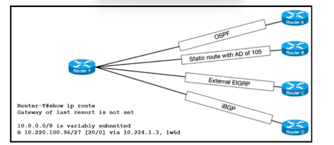
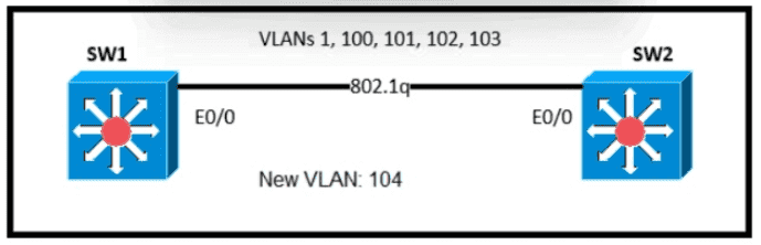
IP connectivity between the three routers is configured. OSPF adjacencies must be established.
1. Configure R1 and R2 Router IDs using the interface IP addresses from the link that is shared between them.
2. Configure the R2 links with a max value facing R1 and R3. R2 must become the DR. R1 and R3 links facing R2 must remain with the default OSPF configuration for DR election. Verify the configuration after clearing the OSPF process.
3. Using a host wildcard mask, configure all three routers to advertise their respective Loopback1 networks.
4. Configure the link between R1 and R3 to disable their ability to add other OSPF routers.
Answer : A
Answer as below configuration:
on R1
conf terminal
interface Loopback0
ip address 10.10.1.1 255.255.255.255
!
interface Loopback1
ip address 192.168.1.1 255.255.255.0
!
interface Ethernet0/0
no shut
ip address 10.10.12.1 255.255.255.0
ip ospf 1 area 0
duplex auto
!
interface Ethernet0/1
no shut
ip address 10.10.13.1 255.255.255.0
ip ospf 1 area 0
duplex auto
!
router ospf 1
router-id 10.10.12.1
network 10.10.1.1 0.0.0.0 area 0
network 192.168.1.0 0.0.0.255 area 0
!
copy run star
---------------------------------------
On R2
conf terminal
interface Loopback0
ip address 10.10.2.2 255.255.255.255
!
interface Loopback1
ip address 192.168.2.2 255.255.255.0
!
interface Ethernet0/0
no shut
ip address 10.10.12.2 255.255.255.0
ip ospf priority 255
ip ospf 1 area 0
duplex auto
!
interface Ethernet0/2
no shut
ip address 10.10.23.2 255.255.255.0
ip ospf priority 255
ip ospf 1 area 0
duplex auto
!
router ospf 1
network 10.10.2.2 0.0.0.0 area 0
network 192.168.2.0 0.0.0.255 area 0
!
copy runs start
-----------------------
On R3
conf ter
interface Loopback0
ip address 10.10.3.3 255.255.255.255
!
interface Loopback1
ip address 192.168.3.3 255.255.255.0
!
interface Ethernet0/1
no shut
ip address 10.10.13.3 255.255.255.0
ip ospf 1 area 0
duplex auto
!
interface Ethernet0/2
no shut
ip address 10.10.23.3 255.255.255.0
ip ospf 1 area 0
duplex auto
!
router ospf 1
network 10.10.3.3 0.0.0.0 area 0
network 192.168.3.0 0.0.0.255 area 0
!
copy run start
!
What are two reasons to implement DHCP in a network? (Choose two.)
Answer : D, E
Topic 5, Simulations / Lab
An on-site service desk technician must verify the IP address and DNS server information on a users Windows computer. Which command must the technician enter at the command prompt on the user's computer?
What is the operating mode and role of a backup port on a shared LAN segment in Rapid PVST+?
Answer : C