Page: 1
/ 14
Total 49 questions
Dell EMC Dell PowerMax Operate v.2 D-PVM-OE-01 Exam Questions
Question 1
Two PowerMax arrays have been configured for replication using SRDF During a disaster recovery operation production has been transferred to the R2 devices at the target site
Which operation allows the primary hosts to access the R1 devices without waiting for a data transfer to complete from the R2 devices'?
Answer : D
Step by Step Comprehensive Detailed
In an SRDF (Symmetrix Remote Data Facility) disaster recovery scenario where production has been switched to the R2 devices at the target site, the Resume operation allows the primary hosts to regain access to the R1 devices without waiting for a full data transfer from the R2 devices.
Here's how it works:
R1 Access: The Resume operation makes the R1 devices (at the primary site) accessible to the primary hosts.
Background Synchronization: While the hosts access and modify data on the R1 devices, SRDF continues to synchronize the changes from the R2 devices (at the target site) in the background. This ensures that the R1 devices are gradually updated with any changes that occurred on the R2 devices during the failover.
This approach minimizes downtime and allows for a quicker return to the primary site without waiting for a lengthy synchronization process to complete before granting host access.
Why other options are incorrect:
A . Update: This operation copies changes from R2 to R1, but it doesn't necessarily grant immediate host access to R1.
B . Fallback: This is a more comprehensive process that involves reversing replication direction and fully restoring the primary site as the production environment.
C . Failover: This operation switches production to the R2 devices, not the R1 devices.
Reference and documents of Dell's public documentation for PowerMax Operate v.2:
Dell Solutions Enabler 10.0.0 SRDF Family CLI User Guide: This guide provides detailed information about SRDF commands and operations, including the symrdf resume command. You can find this document on the Dell Support website by searching for 'Solutions Enabler SRDF Family CLI User Guide.'
Dell PowerMax Family: Essentials and Best Practices Guide: This guide offers a comprehensive overview of SRDF and its functionalities, including disaster recovery scenarios and the use of the 'Resume' operation.
Question 2
SIMULATION
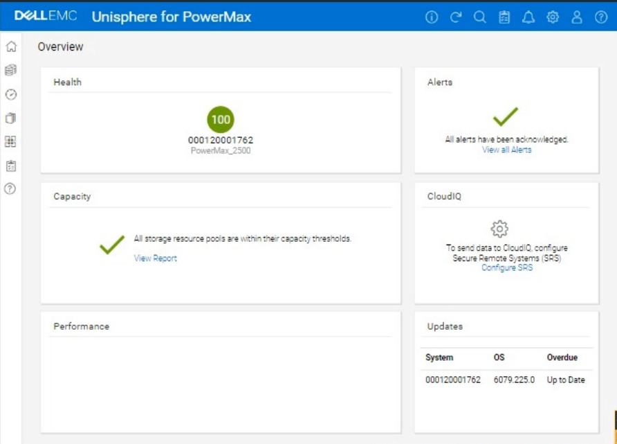
A company is preparing for a major product launch and a quarterly compliance audit. Perform a system health check to ensure that the storage array with SID - 1762 is functioning optimally, and also review the compliance status, generate and download the compliance report for all SGs.
Use the simulator to complete these tasks.
Answer : A
Okay, I understand. We need to perform a system health check and review the compliance status for a PowerMax array with SID ending in 1762 using the Unisphere simulator, then generate and download a compliance report.
Here's how you would do it in the Unisphere for PowerMax simulator, based on the provided image and common Unisphere functionality:
Steps:
1. Launch the Simulator and Access the System Health View
Open Unisphere for PowerMax in your web browser.
You should already be logged in to the simulator, with the PowerMax array with SID 1762.
The initial Overview page (as shown in the image) provides a good starting point for a health check.
2. Analyze the Overview Page
Health: The 'Health' section displays the overall health status of the array. In the image, it shows '100' with a green checkmark, which indicates that the array is currently healthy.
Alerts: The 'Alerts' section will show if there are any active alerts. In the image, it shows a green checkmark and 'All alerts have been acknowledged,' meaning no unacknowledged alerts. You can click 'View all Alerts' to see the alert history.
Capacity: The 'Capacity' section indicates whether storage resource pools are within their capacity thresholds. The green checkmark and 'All storage resource pools are within their capacity thresholds' message indicate that capacity is currently healthy. You can click 'View Report' for more details.
Performance: The 'Performance' section is not detailed in the image, but it would typically provide a quick overview of the array's performance.
Updates: The 'Updates' section shows the system's PowerMaxOS code level and whether any updates are overdue. In the image, it shows that the system is 'Up to Date.'
3. Navigate to the Compliance Section
In the left-hand navigation pane, click on Data Protection to expand it.
Click on Compliance under Data Protection.
4. Review Compliance Status
The Compliance view will show you the overall compliance status of your storage groups against the defined compliance policies.
Review the compliance status for each Storage Group.
Look for any storage groups that are marked as 'Non-Compliant.'
5. Generate the Compliance Report
Click on 'Generate Report' (or a similarly worded button) within the Compliance view. This might also be represented as an icon in the simulator.
Select all Storage Groups Since we need to generate the report for all storage groups.
Report Format: Choose the desired report format. Common options are usually PDF, CSV, or HTML. For this simulation, let's assume PDF is available and select it.
Download the Report: Once the report is generated, there will typically be a 'Download' or similar option to save the report to your local system. Click it to download the compliance report.
6. Further Health Checks (Optional):
Detailed Performance Metrics: You can navigate to the Performance section in the left navigation pane (under 'Dashboard') to view more detailed performance metrics for various components of the array.
Hardware Status: You can typically find a 'Hardware' section (or similarly named section) that provides information about the physical components of the array (e.g., DAEs, directors, ports).
Question 3
What is the largest TDEV PowerMaxOS 5978 can create?
Answer : B
Step by Step Comprehensive Detailed
In PowerMaxOS 5978, the largest TDEV (Thin Device) that can be created is 64 TB. This represents the maximum size for a single, thinly provisioned storage volume on a PowerMax array running that version of the operating system.
Reference and documents of Dell's public documentation for PowerMax Operate v.2:
Dell PowerMax Family: Essentials and Best Practices Guide: This guide provides an overview of PowerMax features and capabilities, including information about storage device sizes and limits.
Dell Solutions Enabler 10.0.0 CLI User Guide: This guide might contain details about the maximum size of TDEVs that can be created using SYMCLI commands.
Topic 2,
SIMULATION
Question 4
What is the functionality of the storstpd Solutions Enabler daemon?
Answer : A
Step by Step Comprehensive Detailed
Solutions Enabler (SE) uses various daemons (background processes) to perform different functions. The storstpd daemon is specifically responsible for:
Collecting Performance Statistics: It gathers performance data from the connected storage arrays, such as I/O rates, response times, and other metrics.
Managing Performance Data: It stores and manages the collected performance statistics, making them available for monitoring and analysis through tools like Unisphere for PowerMax.
This data is crucial for understanding the performance of the storage arrays, identifying potential bottlenecks, and optimizing storage resources.
Why other options are incorrect:
B . Coordinates storage array locks and application syscalls: This is the function of the storapid daemon.
C . Starts the system watchdog timer periodically: This is not directly related to the storstpd daemon.
D . Performs remote Solutions Enabler API functions: This is typically handled by the storsrvd daemon.
Reference and documents of Dell's public documentation for PowerMax Operate v.2:
Dell Solutions Enabler 10.0.0 CLI User Guide: This guide provides information about the different daemons used by Solutions Enabler and their roles. You can find this document on the Dell Support website by searching for 'Solutions Enabler CLI User Guide.'
Question 5
An administrator is using the Workload Planner feature in Unisphere for PowerMax
How does the Planner calculate if the Storage Group workload is stable?
Answer : D
Step by Step Comprehensive Detailed
The Workload Planner in Unisphere for PowerMax helps you analyze and predict the performance impact of adding new workloads to your storage array. It uses sophisticated algorithms to calculate how the addition of a new workload will affect the existing workloads and whether it will violate any service level objectives (SLOs).
To determine if a Storage Group workload is stable, the Planner considers two key calculated values:
Read Response Time: The predicted read response time of the Storage Group after the new workload is added.
Write Response Time: The predicted write response time of the Storage Group after the new workload is added.
The Planner compares these calculated values against the service level (SL) defined for the Storage Group. If both the calculated read and write response times fall within the defined SL response time, the Planner considers the workload to be stable. This means that the new workload can be added without negatively impacting the performance of the existing workloads or violating the SLOs.
Why other options are incorrect:
A . One of the calculated values is within 10-20% of the SL-defined response time: Both read and write response times must be within the defined SL, not just one.
B . Both calculated values are within a 10-15% threshold of the SL-defined response time: The threshold is not fixed at 10-15%. The calculated values must be within the actual SL-defined response time.
C . One of the calculated values remains within the SL-defined response time: Again, both read and write response times need to be within the defined SL.
Reference and documents of Dell's public documentation for PowerMax Operate v.2:
Dell Unisphere for PowerMax 10.0.0 Online Help: The online help for Unisphere provides detailed information about the Workload Planner feature, including how it calculates and analyzes workload stability. You can access this help within Unisphere itself or on the Dell Support website.
Dell PowerMax Family: Essentials and Best Practices Guide: This guide may offer general information about performance management and workload planning in PowerMax, providing context for understanding the Workload Planner's functionality.
Question 6
What function does the storsrvd daemon support?
Answer : D
The storsrvd daemon is a critical component of the Solutions Enabler (SYMCLI) software suite used to manage Dell PowerMax and VMAX storage arrays. Its primary function is to:
Listen for SYMAPI Sessions: It acts as a communication endpoint, listening for incoming SYMAPI sessions from clients or management tools like Unisphere.
Handle Management Requests: When a client connects, storsrvd receives and processes SYMAPI commands and requests, forwarding them to the appropriate components within Solutions Enabler for execution.
Essentially, storsrvd acts as an intermediary between SYMCLI clients and the storage array, facilitating communication and management operations.
Why other options are incorrect:
A . Manages Composite Groups and Device Groups: This is handled by other components within Solutions Enabler.
B . Provides centralized gatekeeper device management: While storsrvd plays a role in device management, it's not the sole component responsible for it.
C . Provides replication consistency protection: This is a function of SRDF (Symmetrix Remote Data Facility) and related components.
Reference and documents of Dell's public documentation for PowerMax Operate v.2:
Dell Solutions Enabler 10.0.0 CLI User Guide: This guide provides information about the architecture and components of Solutions Enabler, including the role of the storsrvd daemon in handling SYMAPI communication. You can find this document on the Dell Support website by searching for 'Solutions Enabler CLI User Guide.'
Question 7
A Storage Group is serving host read/write I/O. The Storage Administrator started an MDM migration and ran a symdm sync -stop command, putting the migration in a CutoverNoSync migration state
Where does the customer data in the Storage Group reside?
Answer : C
Step by Step Comprehensive Detailed
In an MDM (Migration for Dell EMC) migration, data is moved from a source array to a target array. When the symdm sync -stop command is issued, it puts the migration into the CutoverNoSync state. This state signifies that:
Synchronization Stopped: Active data synchronization between the source and target arrays has been stopped.
Data on Both Arrays: However, the customer data still resides on both the source and target arrays. This is because the CutoverNoSync state is a transitional state that allows for a controlled cutover to the target array.
The next step would typically involve a cutover operation, where host access is switched to the target array, and the source array is removed from the migration configuration.
Why other options are incorrect:
A . Only the target array: While the goal is to eventually have the data only on the target, in the CutoverNoSync state, data still exists on both arrays.
B . Only on the source array: Data has already been partially or fully copied to the target array during the migration process.
Reference and documents of Dell's public documentation for PowerMax Operate v.2:
Dell Solutions Enabler 10.0.0 CLI User Guide: This guide provides detailed information about the symdm command and its various options, including the sync -stop command and the CutoverNoSync state. You can find this document on the Dell Support website by searching for 'Solutions Enabler CLI User Guide.'
Dell PowerMax Family: Essentials and Best Practices Guide: This guide may offer general information about data migration and the different states involved in the process.