Page: 1
/ 14
Total 55 questions
Fortinet NSE 6 - FortiSwitch 7.2 NSE6_FSW-7.2 Exam Questions
Question 1
How are the 'by VLAN redirect MAC address quarantine' mode and the 'by redirect MAC address quarantine' mode on FortiGate similar?
Answer : A
The 'by VLAN redirect MAC address quarantine' mode and the 'by redirect MAC address quarantine' mode on FortiGate share specific similarities:
Quarantine VLAN Assignment (A):
Common Feature: Both modes utilize a designated quarantine VLAN to isolate quarantined devices. This helps in mitigating the risk of spreading potential security threats within the network.
Operational Impact: Moving devices to a specific quarantine VLAN restricts their network access, effectively isolating them until further action or remediation is taken.
Question 2
Which statement about the use of the switch port analyzer (SPAN) packet capture method is true?
Answer : A
The correct statement about using the Switch Port Analyzer (SPAN) packet capture method on FortiSwitch is that 'Mirrored traffic can be sent across multiple switches (A).' This feature allows for extensive traffic analysis as it enables network administrators to configure SPAN sessions that span across different switches, thereby providing the capability to monitor traffic across a broad segment of the network infrastructure.
Question 3
Which LLDP-MED Type-Length-Values does FortiSwitch collect from endpoints to track network devices and determine their characteristics?
Answer : D
While FortiSwitch can collect all the listed LLDP-MED TLVs (Network Policy, Power Management, Location, and Inventory Management), the primary focus for tracking and identifying network devices is on the Inventory Management TLV.
This TLV carries critical details such as:
Manufacturer
Model
Hardware/Firmware versions
Serial/Asset numbers
This information provides a granular understanding of the devices on your network.
Question 4
Refer to the exhibits.
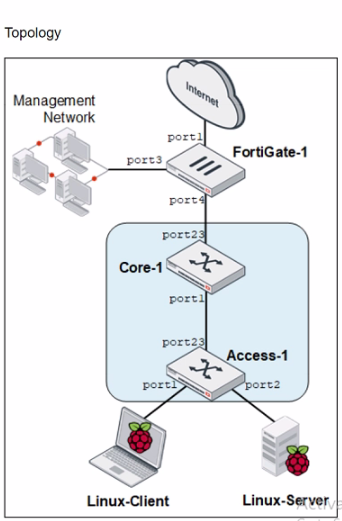
You are asked to ensure that managed FortiSwitch devices are reachable by other devices, such as SNMP and other management tools across your network.
Which setting must you configure to ensure traffic from other devices in the network reaches FortiSwitch?
Answer : B
Question 5
Refer to the exhibit.
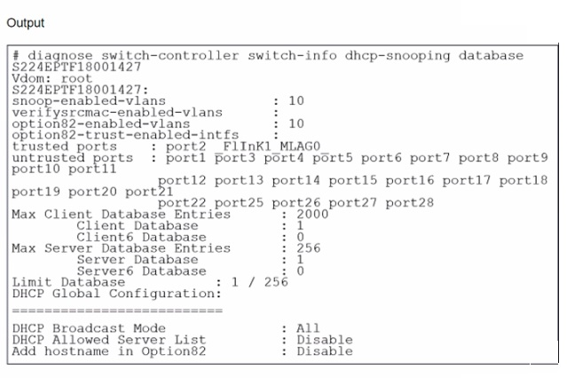
What two conclusions can be made regarding DHCP snooping configuration? (Choose two.)
Answer : B, D
Based on the DHCP snooping configuration details provided in the exhibit:
B . FortiSwitch is configured to trust DHCP replies coming on FortiLink interface. The configuration segment shows 'trusted ports : port2 FlInK1 MLAG0,' indicating that the FortiSwitch is configured to trust DHCP replies coming from the specified ports, including the FortiLink interface labeled FlInK1. This setup is critical in environments where the FortiLink interface connects directly to a trusted device, such as a FortiGate appliance, ensuring that DHCP traffic on these ports is considered legitimate.
D . Global configuration for DHCP snooping is set to forward DHCP client requests on all ports in the VLAN. The 'DHCP Broadcast Mode' set to 'All' under the DHCP Global Configuration indicates that DHCP client requests are allowed to broadcast across all ports within the VLAN. This setting is essential for environments needing broad DHCP client servicing across multiple access ports without restriction, facilitating network connectivity and management.
Question 6
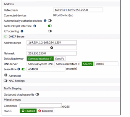
Refer to the configuration:
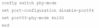
Which two conditions does FortiSwitch need to meet to successfully configure the options shown in the exhibit above? (Choose two.)
Answer : A, B
Question 7
Exhibit.
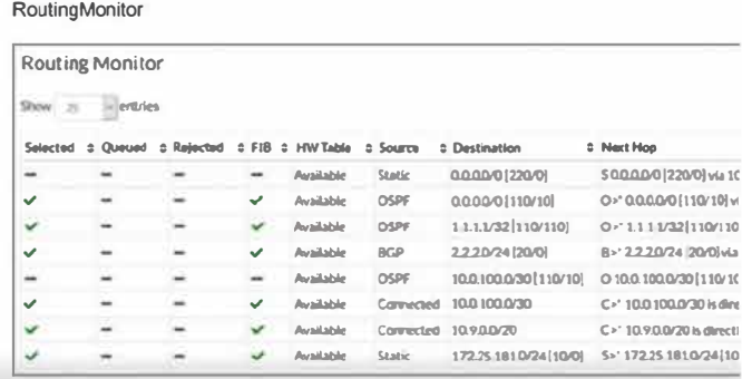
Two routes are not installed in the forwarding information base (FIB) as shown in the exnibit. Which two statements about these two route entries are true? (Choose two.)
Answer : A, B
From the exhibit and the details given about the routes not installed in the FIB:
These two routes have a higher administrative distance value available to the destination networks (Option A): Administrative distance is a measure used by routers to select the best path when there are two or more different routes to the same destination from two different routing protocols. A higher administrative distance means that the route is considered less trustworthy, thus not selected for the FIB unless the more preferred routes fail.
These two routes will become primary, if the best routes are removed (Option B): In routing, if the currently installed routes (which are considered the best due to reasons like lower administrative distance) are removed or become unavailable, the next best routes based on administrative distance will be used. This behavior ensures redundancy and maintains network connectivity in diverse scenarios.
This approach is aligned with standard routing protocol behavior as documented in networking protocols and Fortinet's routing mechanisms which prioritize routes based on administrative distance and other metrics to maintain efficient and reliable network routing.