Page: 1
/ 14
Total 156 questions
Huawei HCIP-Datacom-Advanced Routing & Switching Technology V1.0 H12-831_V1.0 Exam Questions
Question 1
Fill in blank
VLAN aggregation is configured on a switched network. Sub-VLAN 2 and Sub-VLAN 3 are added to Super-VLAN 10.
To enable hosts in different Sub-VLANs to communicate with each other, run the _____ inter-sub-vlan-proxy enable command in the view of VLANIF 10, corresponding to the Super-VLAN.
(Enter the answer in lowercase letters only.)
Answer : A
1. Understanding VLAN Aggregation in Huawei Switches
VLAN aggregation is a technique that groups multiple VLANs (sub-VLANs) under a single Super-VLAN.
Super-VLANs do not have member interfaces but include multiple Sub-VLANs that share a common gateway (VLANIF interface).
2. Inter-Sub-VLAN Communication Requirement
By default, hosts in different sub-VLANs cannot communicate directly.
To enable communication between different sub-VLANs within the same Super-VLAN, an inter-sub-VLAN proxy must be enabled.
This is done using the inter-sub-vlan-proxy enable command in the VLANIF interface of the Super-VLAN.
3. Correct Command Usage
The command format is:
shell
CopyEdit
supervlan inter-sub-vlan-proxy enable
This command must be executed under VLANIF 10, corresponding to the Super-VLAN.
4. Why is the Answer 'supervlan'?
The missing parameter in the command should be supervlan, because it is used to enable communication between Sub-VLANs under a Super-VLAN.
This is a specific Huawei command used in HCIP-Datacom-Advanced Routing & Switching Technology certification.
Question 2
The figure shows information about VPN1 on a PE (Provider Edge) router in a BGP/MPLS IP VPN network.
When the VPNv4 route corresponding to VPN1 is advertised to the remote PE, which VPNs of the remote PE will accept the route?
VPN1 Configuration:
ip vpn-instance VPN1
ipv4-family
route-distinguisher 100:1
vpn-target 100:1 200:1 300:1 export-extcommunity
VPN Import Policies on the Remote PE:
Answer : A
Comprehensive and Detailed In-Depth
1. Understanding Route Targets (RT) and Route Distribution in MPLS VPN
MPLS Layer 3 VPNs (L3VPNs) use BGP to distribute VPN routes across multiple Provider Edge (PE) routers.
Each VPN instance (VRF) is configured with Route Targets (RTs) to control which VPN routes are imported/exported.
Route Distinguishers (RDs) are unique per VRF but do not affect route selection.
2. Analyzing VPN1 Configuration
VPN1 is exporting routes with the following Route Targets (vpn-target values):
100:1
200:1
300:1
Remote VPNs will import these routes only if their import RT list matches one of the exported RTs.
3. Matching Exported RTs with Import RTs in Remote VPNs
Remote VPN
Import RTs
Matches VPN1 Exported RTs (100:1, 200:1, 300:1)?
Accepts the Route?
VPN1
100:1
Matches 100:1
Yes
VPN2
200:1, 400:1
Matches 200:1
Yes
VPN3
100:1, 300:1
Matches 100:1, 300:1
Yes
VPN4
500:1
No match
No
VPN1, VPN2, and VPN3 accept the route.
VPN4 does not accept the route because 500:1 is not in the export list of VPN1.
Final Conclusion:
Correct Answe r : VPN1, VPN2, and VPN3 will accept the route.
VPN4 does not accept the route because there is no matching RT.
Thus, the correct answer is:
A. VPN1: Import RT=100:1
B. VPN2: Import RT=200:1, 400:1
C. VPN3: Import RT=100:1, 300:1
D. VPN4: Import RT=500:1 (No match, does not accept the route).
HCIP-Datacom-Advanced Routing & Switching Technology V1.0 -- MPLS VPN Route Target and Route Filtering
Huawei Official HCIP-Datacom Study Guide -- BGP/MPLS VPN Import/Export Mechanisms
Huawei Documentation on MPLS VPN Route Distinguisher (RD) and Route Target (RT) Concepts
Question 3
Fill in blank
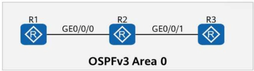
On the OSPFv3 network shown in the figure, the LSDB of R2 contains ____ Router-LSAs. (Enter only digits.)
Answer : A
To determine the correct answer, we need to analyze how OSPFv3 handles Router LSAs (Type 1 LSAs) in a simple Area 0 topology like the one shown in the figure.
1. Understanding OSPFv3 Router LSAs (Type 1 LSAs)
Router LSAs (Type 1 LSAs) are generated by each router within an OSPF area to describe its own directly connected links.
Each router in an OSPF area generates exactly one Type 1 LSA.
The Link-State Database (LSDB) on a router contains LSAs from all routers in the same area.
2. Analyzing the Network in the Figure
There are 3 routers: R1, R2, and R3.
All routers are in OSPFv3 Area 0 (which is a single area).
Each of these routers generates one Router LSA (Type 1 LSA).
Since R2 is in the same area as R1 and R3, its LSDB contains the Router LSAs from itself, R1, and R3.
3. Conclusion
The LSDB of R2 contains 3 Router LSAs (one from each router: R1, R2, and R3).
Final Answer: 3
Question 4
On a BGP/MPLS IP VPN network, VPNv4 routes carry the export RT. Which of the following attributes is used by MP-BGP to carry the export RT?
Answer : A
Question 5
On the network shown in the figure, SW3 is the user gateway and DHCP relay agent.
The administrator plans to configure DHCP snooping on SW3 to prevent DHCP attacks.
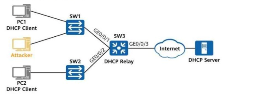
Which of the following commands does not need to be configured on SW3?
Answer : B
Comprehensive and Detailed In-Depth
Understanding DHCP Snooping and its Configuration
1. What is DHCP Snooping?
DHCP Snooping is a security feature that helps prevent rogue DHCP servers from providing false IP configurations to clients.
It classifies switch ports as either:
Trusted (allowing DHCP replies from legitimate DHCP servers or relay agents).
Untrusted (blocking unauthorized DHCP responses from clients or attackers).
Analysis of the Commands
A. [SW3-GigabitEthernet0/0/2] dhcp snooping enable (Required)
Interface GigabitEthernet0/0/2 is connected to a DHCP client (PC2).
DHCP snooping must be enabled on this interface to filter DHCP messages and prevent rogue DHCP servers.
Since PC2 is a client, this port should remain UNTRUSTED.
This command is required.
B. [SW3] dhcp snooping enable ipv4 (Not Required - Correct Answer)
The correct command to enable DHCP Snooping globally on Huawei switches is:
dhcp snooping enable
There is no need to explicitly specify ipv4 since DHCP is inherently an IPv4-based protocol.
This command is unnecessary, making it the correct answer.
C. [SW3-GigabitEthernet0/0/3] dhcp snooping trusted (Required)
GigabitEthernet0/0/3 is connected to the DHCP relay agent, which forwards DHCP messages between clients and the DHCP server.
This port must be configured as 'trusted' to allow DHCP responses from the relay or the DHCP server.
This command is required.
D. [SW3-GigabitEthernet0/0/1] dhcp snooping enable (Required)
GigabitEthernet0/0/1 is connected to a DHCP client (PC1).
Similar to Port 0/0/2, DHCP snooping must be enabled on this interface to filter DHCP messages and prevent rogue DHCP responses.
This command is required.
Final Conclusion:
A. Required (PC2's port needs DHCP snooping enabled).
B. Not required (Incorrect command syntax, ipv4 is unnecessary).
C. Required (Port connected to DHCP relay must be trusted).
D. Required (PC1's port needs DHCP snooping enabled).
Thus, the correct answer is: B. [SW3] dhcp snooping enable ipv4.
HCIP-Datacom-Advanced Routing & Switching Technology V1.0 -- DHCP Snooping Configuration and Security Mechanisms
Huawei Official HCIP-Datacom Study Guide -- DHCP Snooping on L2 and L3 Switches
Huawei Documentation on Configuring DHCP Snooping in Enterprise Networks
Question 6
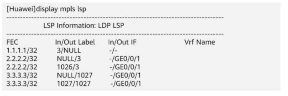
An administrator runs the display mpls lsp command to view LSPs on a device. The command output is shown in the figure.
Which of the following statements is true?
Options:
Answer : D
Comprehensive and Detailed In-Depth
1. Understanding MPLS Label Forwarding Information
The output of the display mpls lsp command shows the Label Forwarding Information Base (LFIB) used by the router to forward MPLS packets.
Each entry consists of:
FEC (Forwarding Equivalence Class): The destination IP prefix.
In Label / Out Label: Incoming label (received) and outgoing label (sent).
In IF / Out IF: Incoming and outgoing interfaces.
2. Analyzing the Given LSP Table
FEC (Destination IP)
In Label
Out Label
Outgoing Interface
1.1.1.1/32
3
NULL
-
2.2.2.2/32
NULL
3
GE0/0/1
2.2.2.2/32
1026
3
GE0/0/1
3.3.3.3/32
NULL
1027
GE0/0/1
3.3.3.3/32
1027
1027
GE0/0/1
Key Observations:
NULL means the label is removed (Penultimate Hop Popping - PHP).
Label 3 is the implicit null label, meaning the label is removed before sending to the next router.
For destination 3.3.3.3, the router adds label 1027 before forwarding it to GE0/0/1.
3. Evaluating Each Answer Option
Option A: 'Before forwarding a packet destined for 2.2.2.2, the device adds label 3 to the packet.' Incorrect.
The output shows that packets destined for 2.2.2.2 have the NULL (label 3) entry, which means the label is removed before forwarding, not added.
Option B: 'Before forwarding a packet destined for 1.1.1.1, the device adds label 3 to the packet.' Incorrect.
The entry 1.1.1.1 3/NULL means the label is removed (PHP), so the device does not add label 3.
Option C: 'Before forwarding a packet destined for any IP address, the device removes labels from the packet.' Incorrect.
The device removes labels only for some destinations (e.g., 1.1.1.1 and 2.2.2.2), but it adds label 1027 for 3.3.3.3.
Not all IPs have their labels removed.
Option D: 'Before forwarding a packet destined for 3.3.3.3, the device adds label 1027 to the packet.' Correct.
The entry 3.3.3.3 NULL/1027 means that the router adds label 1027 before forwarding packets to GE0/0/1.
Final Answer:
Answer : D (Before forwarding a packet destined for 3.3.3.3, the device adds label 1027 to the packet).
HCIP-Datacom-Advanced Routing & Switching Technology Reference:
Understanding MPLS LDP (Label Distribution Protocol) and LFIB
Implicit Null (Label 3) and Penultimate Hop Popping (PHP)
MPLS Label Swapping and Forwarding Process
Question 7
On a stable network that requires fast route convergence, you can change the value of the interval at which OSPF LSAs are updated to 0 so that topology or route changes can be immediately advertised on the network through LSAs, which speeds up route convergence.
Answer : A