Page: 1
/ 14
Total 67 questions
Juniper Data Center, Associate JN0-281 Exam Questions
Question 1
You have configured nonstop active routing NSR and want to verify the status of the synchronization including which protocols are configured for NSR support. Which command would you use to accomplish this task?
Answer : A
Nonstop active routing relies on control-plane state synchronization between the primary and backup Routing Engines so that routing protocol operation can continue across a switchover. To verify whether that synchronization is occurring and to see which protocol processes are participating, Junos provides visibility into the underlying replication framework. The command show task replication displays replication status and synchronization details for replicated tasks, which commonly include routing-related processes when NSR is enabled. This output helps confirm whether the backup Routing Engine is receiving the necessary state updates and whether replication is in sync, catching up, or experiencing issues.
This is the most direct operational validation because NSR effectiveness depends on ongoing state replication. Simply checking general switchover readiness does not prove protocol state is synchronized. Likewise, listing system services does not confirm replication or identify which routing protocols are actively supported for nonstop behavior. High availability statistics under services are oriented toward service-specific HA functions and do not provide the routing protocol replication view that NSR troubleshooting typically requires.
In data center fabrics where underlay routing stability is critical, routinely checking task replication status is a practical way to verify that NSR is actually providing the intended resilience before you perform maintenance or experience an unplanned Routing Engine event.
Verification sources from Juniper documentation
https://www.juniper.net/documentation/us/en/software/junos/high-availability/topics/topic-map/nonstop-active-routing-understanding.html
https://www.juniper.net/documentation/us/en/software/junos/high-availability/topics/reference/command/show-task-replication.html
Question 2
What are two characteristics of EBGP? Choose two.
Answer : A, D
EBGP is the BGP session type formed between different autonomous systems. In Juniper data center IP fabrics, EBGP is frequently used for the underlay because it can provide all required reachability without an additional interior gateway protocol. The fabric can advertise loopbacks and point-to-point link subnets directly in BGP, then use ECMP to install multiple equal-cost next hops. This is why EBGP sessions do not require an IGP as a fundamental dependency. Some designs still add an IGP for other reasons, but EBGP itself can carry the underlay routes needed for full fabric connectivity.
EBGP sessions are also typically established between directly connected peers. In a standard leaf-spine underlay, each leaf peers with each spine over the routed physical links between them, using the interface IP addresses on those point-to-point subnets. This matches EBGP default behavior, including a one-hop TTL expectation and straightforward operational troubleshooting.
Loopback peering is not required for EBGP. It is possible, but it usually needs additional configuration such as multihop and a routing method to ensure reachability to the remote loopback before the BGP session can form. EBGP also supports sessions with non-directly connected peers when multihop is configured, so it is incorrect to claim EBGP does not support that capability.
Question 3
By default, which two statements about trunk and access ports are correct? Choose two.
Answer : B, D
On Junos Ethernet switching, access and trunk ports serve different purposes and therefore treat VLAN tags differently by default. An access port is intended for a single VLAN and is designed to connect to endpoints that do not tag their frames. Because of that, access ports forward traffic as untagged on the wire and internally associate those untagged frames to the configured access VLAN. This makes access ports the standard choice for single-VLAN server NICs, management devices, and any endpoint expecting a plain Ethernet connection.
A trunk port is intended to carry traffic for multiple VLANs over a single link, which is typical for switch-to-switch uplinks, leaf-to-spine connectivity where VLAN services are extended, and hosts or appliances that use VLAN tagging. By default, trunk ports forward tagged traffic and require VLAN tags to identify the VLAN membership of each frame. Untagged behavior on a trunk is not assumed by default and is typically governed by configuring a native VLAN or equivalent untagged VLAN handling, depending on platform and design. Without such configuration, untagged frames are not treated as a normal expected case for a trunk link in data center fabrics.
Therefore, the correct default statements are that access ports forward untagged traffic and trunk ports forward tagged traffic, matching options B and D.
Question 4
In a three-stage IP fabric, what is the sequence of fabric node stages that a packet passes through?
Answer : A
A three-stage IP fabric is a scaled leaf-spine design that adds an additional layer above the spine layer to increase port scale and bandwidth. In common data center terminology, the stages are leaf, spine, and an upper spine layer often referred to as superspine. Traffic sourced from an endpoint attached to a leaf switch first enters the fabric at that leaf. If the destination is attached to a different leaf and the fabric is truly three-stage, the packet typically traverses from the source leaf up to a spine, then continues upward to the upper layer spine, then down to a destination spine, and finally down to the destination leaf. The option that best represents this stage progression is leaf to spine to spine to leaf, where the second spine in the sequence corresponds to the upper layer spine tier in a three-stage design.
By contrast, leaf to spine to leaf describes a two-tier leaf-spine fabric where a single spine hop connects any two leaves. The other options do not represent the standard end-to-end progression for traffic between leaves in a three-stage fabric. In practice, the underlay uses routed links with equal-cost multipath, so there can be multiple equal paths that still follow the same stage order. This preserves predictable forwarding behavior while allowing the fabric to scale beyond what a two-tier topology can support.
Question 5
Referring to the exhibit, which type of protocol session will be established?
Answer : D
The configuration shown is under protocols bgp and defines a BGP group named service-pod with the statement type internal. In Junos, the BGP group type determines whether the sessions formed by neighbors in that group are treated as internal BGP or external BGP. When the group is set to type internal, the router establishes an iBGP session to the configured neighbor address. That means both peers are expected to be in the same autonomous system, and the session is used to exchange routes within that single AS.
The local-address statement sets the source address that the router will use when initiating the TCP connection for BGP. In data center designs, this is commonly a loopback address so the session can be resilient and independent of any single physical interface. The neighbor statement identifies the remote peer address. With type internal, the session is iBGP even if the neighbor is directly connected, because the relationship is defined by AS scope rather than topology.
OSPF and IS-IS are different routing protocols entirely and are not established through BGP configuration. EBGP would require type external and typically involves different AS numbers across the peering. Therefore, the only correct answer is IBGP.
Question 6
Exhibit:
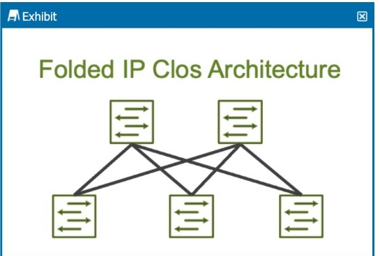
How many stages are shown in the exhibit?
Answer : D
The exhibit shows a Folded IP Clos Architecture, which is also referred to as a 3-stage Clos network design. This architecture typically consists of two layers of switches:
Spine Layer: The top row of switches.
Leaf Layer: The bottom row of switches.
Step-by-Step Breakdown:
Clos Architecture:
A 3-stage Clos network has two types of devices: spine and leaf. In this design, each leaf switch connects to every spine switch, providing a high level of redundancy and load balancing.
Stage Explanation:
Stage 1: The first set of leaf switches.
Stage 2: The spine switches.
Stage 3: The second set of leaf switches.
The Folded Clos architecture shown here effectively 'folds' the 3-stage design by combining the ingress and egress leaf layers into one, reducing it to two visible layers, but still maintaining the overall 3-stage architecture.
Juniper Reference:
IP Clos Architecture: The 3-stage Clos design is commonly used in modern data centers for high availability, redundancy, and scalability.
Question 7
Referring to the exhibit, which statement is correct about the 192.168.1.0/24 route?
Answer : B
The configuration defines a static route for 192.168.1.0/24 with a primary next hop of 10.20.20.254 and a qualified-next-hop of 10.20.20.253 with preference 25. In Junos, qualified next hop is used to create preference-ranked redundancy for a static route, typically primary and backup forwarding. The key behavior is that the best, lowest preference path is selected as active. For static routes, the default preference for the route and its primary next hop is lower than 25 unless you explicitly raise it. Because the qualified-next-hop is configured with preference 25, it is less preferred than the primary next hop, so 10.20.20.254 remains the selected next hop during normal operation.
This is not load balancing. Junos does not automatically install both next hops for forwarding simply because more than one next hop is configured when one is qualified with a higher preference. Instead, the qualified next hop is held in reserve and is used only when the primary next hop becomes unusable, such as when it is no longer resolvable or the associated forwarding condition fails. Therefore, the route is expected to be installed and active using 10.20.20.254 under normal conditions, with 10.20.20.253 acting as a backup path.