Page: 1
/ 14
Total 65 questions
Juniper Enterprise Routing and Switching, Specialist JN0-352 JNCIS-ENT Exam Questions
Question 1
A switch uses the factory-default storm control configuration. A sudden unknown-unicast burst causes packet loss for only 4-5 seconds before stabilizing.
Which statement describes why normal operation resumes automatically?
Answer : D
The factory-default storm control configuration on EX Series switches operates in a purely rate-limiting mode rather than an interface-shutdown mode. When broadcast, multicast, or unknown-unicast traffic on a port exceeds the configured bandwidth-percentage threshold, the default action is simply to police the offending traffic type and silently drop only the packets that exceed that threshold, while all traffic within the allowed rate continues to be forwarded normally and the interface itself remains administratively and operationally up throughout the event. This explains the observed symptom precisely: during the burst of unknown-unicast frames, the switch dropped the excess volume above the configured limit, producing a brief period of packet loss, but as soon as the burst subsided and traffic fell back under the threshold, storm control simply stopped dropping packets and normal forwarding resumed automatically --- no administrative shutdown, recovery timer, or manual intervention was ever involved, because the interface was never taken down in the first place. This default drop-only behavior is distinct from the optional interface-shutdown action, which must be explicitly configured if an administrator wants storm control to disable a port outright on violation (as seen in a related scenario requiring the clear ethernet-switching recovery-timeout command). Storm control by default covers broadcast, multicast, and unknown-unicast traffic types together, not multicast alone, and it has no functional relationship to GRES, which governs Routing Engine redundancy rather than Layer 2 traffic policing. Reference topics: Junos Enterprise Switching -- Storm Control, Default Drop Behavior Versus Interface Shutdown Action.
Question 2
Two Juniper Networks EX Series Switches are connected with four 1-GbE links configured as a single link aggregation group (LAG). One of the physical member links experiences a failure.
By default, what impact will this failure have on traffic forwarding between the switches?
Answer : A
A link aggregation group bundles multiple physical Ethernet links into a single logical interface (an ae interface) specifically to provide both increased aggregate bandwidth and link-level redundancy. By default, the aeX interface remains operationally up as long as at least one member link within the bundle remains active and passing traffic; the LAG does not require every member link to be functional to continue operating. When one of the four 1-GbE member links in this scenario fails, LACP (if in use) or the underlying link-status monitoring detects the failure, removes that specific link from the active forwarding set, and redistributes traffic hashing across the three remaining healthy member links automatically and without operator intervention. End devices and upper-layer protocols continue to see a single, continuously up ae interface throughout this process, experiencing only a proportional reduction in available aggregate bandwidth rather than any interruption in connectivity. This default behavior is precisely why LAG is a foundational building block for resilient EX Series switch interconnects in enterprise and data center designs, since it allows individual optic, cable, or transceiver failures to be absorbed transparently. None of the distractor behaviors --- full administrative shutdown of the bundle, forwarding limited to broadcast traffic only, or a temporary disabling of all member links during renegotiation --- reflect actual Junos LAG behavior, which is designed explicitly to avoid any such disruption. Reference topics: Junos Enterprise Switching -- Layer 2 Switching, Link Aggregation Group Resiliency.
Question 3
[Exhibit]

Click the Exhibit button.
Which three statements about this BGP session are correct? (Choose three.)
Answer : A, B, E
The show route advertising-protocol bgp command displays exactly what would be transmitted to a specific BGP neighbor after all configured export routing policy has already been evaluated and applied, meaning any prefixes shown in this output have successfully passed through the export policy chain --- confirming the export routing policy has been processed. The command header explicitly states '7 destinations, 7 routes (7 active, ...)' and every listed prefix is preceded by an asterisk, Junos's standard marker for an active route, confirming all seven displayed routes are active in the local routing table. The routing table name shown, XYZ.inet.0, indicates these routes reside in a named routing instance called XYZ rather than the default master routing instance, whose table would instead be labeled simply inet.0; this rules out the statement claiming the routes belong to the default instance. The AS path column shows only the origin code 'I' (IGP) with no AS numbers prepended ahead of it, meaning the AS path is empty, which indicates these prefixes were originated locally within R1's own AS (through redistribution or local origination) rather than having been learned from and passed through an external AS, ruling out that statement as well. Finally, the Nexthop column explicitly shows 'Self' for every route rather than an actual peer or learned address, confirming R1 is rewriting the next-hop attribute to its own address before advertising --- a deliberate next-hop-self policy action typically applied toward IBGP peers. Reference topics: Junos Enterprise Routing -- BGP, Verifying Advertised Routes and Export Policy Effects.
Question 4
Which two statements describe OSPF DR and BDR behavior? (Choose two.)
Answer : A, C
The Backup Designated Router exists specifically to provide immediate failover redundancy for the Designated Router role on a multi-access broadcast or NBMA segment: the BDR maintains full adjacencies with every other router on the segment concurrently with the DR, precisely so that if the DR ever fails or is withdrawn, the BDR can be promoted directly to DR essentially instantaneously, without needing to wait through a fresh, full DR/BDR election process, and a new BDR election then takes place separately among the remaining DROther routers to fill the now-vacant backup role. This immediate promotion behavior confirms the first statement as correct. The Designated Router's other core responsibility on the segment is originating the Type 2 Network LSA, which describes the multi-access network itself as a pseudonode, listing every router attached to that segment; this LSA type exists specifically to avoid the full-mesh explosion of Router LSA adjacency listings that would otherwise be needed to describe a shared broadcast segment, and only the DR --- never the BDR, and never any DROther --- is responsible for generating and maintaining this particular LSA under normal, stable conditions, which confirms the third statement while directly ruling out the fourth. There is no such thing as the DR 'electing' an area border router; ABR status is instead a role a router acquires organically by having interfaces in more than one OSPF area, entirely independent of any DR/BDR election process on any individual segment. Reference topics: Junos Enterprise Routing -- OSPF, DR/BDR Roles and Type 2 Network LSA Origination.
Question 5
You are deploying a Juniper Networks EX Series Switch to connect 24 end devices to VLAN 70, with an uplink interface to a distribution switch that carries VLANs 30, 50, and 70. You need to correctly configure the interface type for the end-device interfaces.
In this scenario, which statement is correct?
Answer : D
Each of the 24 end-device-facing interfaces in this scenario needs to carry traffic for exactly one VLAN, and the end devices themselves are ordinary hosts that neither expect nor generate 802.1Q-tagged frames. This is precisely the definition of an access port in Junos: family ethernet-switching interface-mode is set to access, and a single vlan members statement assigns the port to VLAN 70. Access mode ensures frames egressing toward the host are untagged and any frames received are implicitly treated as belonging to the configured VLAN, which is both simpler to manage and more efficient than trunking, since access ports do not carry the 802.1Q tag overhead nor process VLAN pruning logic relevant only to multi-VLAN links. Trunk mode, by contrast, is reserved for switch-to-switch or switch-to-router links that must simultaneously carry frames for multiple VLANs, such as the uplink toward the distribution switch that transports VLANs 30, 50, and 70 together --- configuring the 24 host-facing ports as trunks (with or without a native VLAN) would be functionally incorrect and operationally wasteful, since end devices have no need to interpret VLAN tags. There is also no such behavior in Junos where VLAN-ID numeric value dictates default port behavior, making the 'no configuration needed' option a distractor with no basis in EX Series switching architecture. Reference topics: Junos Enterprise Switching -- VLANs, Configuring Access and Trunk Port Modes.
Question 6
Which sequence correctly describes the basic message flow that leads to a successful BGP peering session?
Answer : B
RFC 4271 defines the BGP finite state machine as a strict, ordered progression of six states that a session must move through to successfully establish. A newly configured or reset session always begins in Idle, where BGP initializes resources and refuses connections until the ConnectRetry timer fires. From Idle, the router transitions to Connect and attempts to establish the underlying TCP transport session to the configured peer address on port 179. If that TCP attempt does not immediately succeed, the session falls back to the Active state, where the router continues retrying the TCP connection in the background; once the TCP handshake finally completes (from either Connect or Active), the session advances to OpenSent, during which the router transmits its own BGP OPEN message advertising its AS number, hold time, BGP identifier, and capabilities. Upon receiving and validating a compatible OPEN message from the peer, the session moves to OpenConfirm, where both sides exchange KEEPALIVE messages to confirm the parameters negotiated in the OPEN exchange are mutually acceptable. Only after this confirmation does the session reach Established, the final state in which UPDATE messages carrying actual routing information begin to flow between the peers. Any deviation from this Idle Connect Active OpenSent OpenConfirm Established ordering, as presented in the other answer choices, does not reflect the standardized BGP state machine. Reference topics: Junos Enterprise Routing -- BGP, The BGP Finite State Machine.
Question 7
[Exhibit]
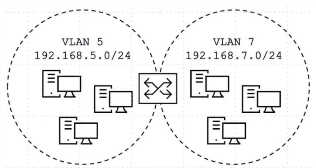
Click the Exhibit button.
Devices on VLAN 5 and VLAN 7 need to communicate with each other.
Referring to the exhibit, what will satisfy this requirement?
Answer : D
VLAN 5 and VLAN 7 are two entirely separate Layer 2 broadcast domains, each with its own distinct IP subnet, and devices in one VLAN can never reach devices in the other through switching alone --- Layer 3 routing between the two subnets is mandatory for any inter-VLAN communication to occur, regardless of how the VLANs are configured at Layer 2. On a single EX Series switch, the correct and standard mechanism for enabling this routing without an external router is to create one integrated routing and bridging (IRB) logical interface for each VLAN, assign each IRB the appropriate gateway IP address for its respective subnet (192.168.5.1 for VLAN 5's irb.5 and 192.168.7.1 for VLAN 7's irb.7, for example), and ensure routing is active on the switch so that traffic arriving at one IRB's gateway address destined for the other VLAN's subnet is routed internally between the two IRB interfaces. Attempting to bind a single family inet interface with two distinct subnet addresses via secondary addressing conflates two separate broadcast domains onto one Layer 3 interface incorrectly and is not how VLAN routing is architected in Junos. Spanning tree exists purely to prevent Layer 2 loops and has no routing function whatsoever, so configuring it cannot enable inter-VLAN reachability. Placing both VLANs on a single trunk with Multiple VLAN Registration Protocol (MVRP) only automates VLAN membership propagation across trunk links; it does not provide any Layer 3 routing capability between the VLANs either. Reference topics: Junos Enterprise Switching -- Routing VLANs, Configuring IRB Interfaces for Inter-VLAN Routing.
 All Official Question Types