Page: 1
/ 14
Total 86 questions
Juniper Service Provider Routing and Switching, Specialist JN0-363 JNCIS-SP Exam Questions
Question 1
Exhibit
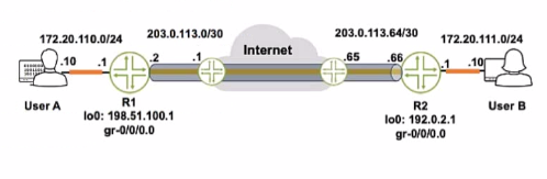
Referring to the exhibit, how do you verify the status of the tunnel from R1?
Answer : B
To verify the status of the tunnel from R1, you would issue a ping from the source address that is assigned to R1's end of the tunnel. In the exhibit, we can see that the tunnel interface (gre-0/0/0.0) has the IP address 198.51.100.1 on R1. Therefore, to test the tunnel's status, you should ping the IP address at the other end of the tunnel (which is likely the address on User B's interface or another interface on R2) from R1's tunnel source address.
Juniper Networks documentation on GRE: GRE Interface Configuration
Question 2
You are deploying link aggregation groups.
Answer : C, E
When deploying Link Aggregation Groups (LAGs), it is necessary for all ports in the LAG to operate at the same speed to ensure consistent performance and avoid issues with load balancing. Multi-Chassis LAG (MC-LAG) allows for the use of member links that span multiple physical devices, offering redundancy and higher bandwidth by combining the links from two separate devices into a single logical LAG.
Juniper Networks Technical Documentation on Link Aggregation Groups
Juniper Networks Technical Documentation on MC-LAG
Question 3
Which new field is added to an IPv6 header as compared lo IPv4?
Answer : D
The IPv6 header includes a new field that is not found in the IPv4 header, called the flow label. The flow label in IPv6 is used to identify packets that require special handling by routers for quality of service (QoS) or other reasons, allowing these packets to be handled efficiently as they move through the network.
Juniper Networks Technical Documentation on IPv6
IPv6 Header Fields - Juniper Networks
Question 4
Which statement is correct about the FE80;:/10 prefix?
Answer : A
The FE80::/10 prefix is reserved for IPv6 link-local addresses. These addresses are auto-configured on all IPv6-enabled interfaces and can be used for communication within the local link (subnet) only.
Juniper Networks Technical Documentation on IPv6 Addressing
Question 5
Exhibit button
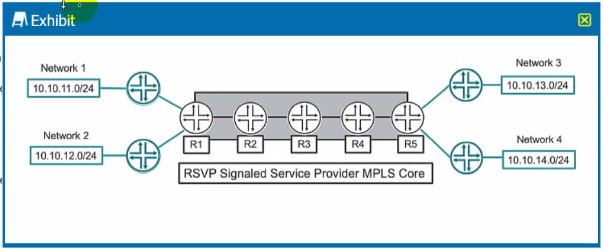
Which two statements are correct about the service provider MPLS network shown in the exhibit? (Choose two.)
Answer : C, D
In MPLS, multiple paths can be merged if they share the same egress router. In the given scenario, traffic from Network 1 to Network 3 and Network 4 can be engineered to follow the same label-switched path (LSP) within the MPLS network until they reach the last common point before diverging to their respective destinations.
As for R3 performing label operations, in a typical MPLS network, intermediate routers (like R3) perform label swapping. They replace the incoming label with a new label before forwarding the packet along the LSP. A label pop operation is typically performed by the egress router in the case of an ultimate hop pop (UHP), where it removes the MPLS label before delivering the packet to the final destination outside the MPLS domain.
Juniper Networks Technical Documentation on MPLS
Understanding MPLS Label Operations (Swap, Push, and Pop) - Juniper Networks
Question 6
What are two types of SlDs used in segment touting? (Choose two.)
Answer : A, B
https://zartmann.dk/sr-intro/
In segment routing, SIDs (Segment Identifiers) are used to identify different types of segments that can be traversed. A node SID represents an instruction to route a packet to a particular node, and an adjacency SID represents an instruction to route a packet over a specific link or adjacency between two nodes.
Juniper Networks Technical Documentation on Segment Routing
Question 7
Exhibit
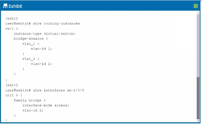
You are asked to assign interface xe-1/0/5 to a virtual switch.
What must be accomplished to complete the configuration?
Answer : A
The exhibit shows the configuration of a virtual switch called sw-1 with two VLANs defined within it: vlan_1 with VLAN ID 1 and vlan_2 with VLAN ID 2. To add interface xe-1/0/5 to the virtual switch, the interface must be associated with one of these VLANs. Since the interface is already configured with vlan-id 2, it implies that it is intended to be part of vlan_2 within the virtual switch sw-1. Therefore, the correct answer is to add interface xe-1/0/5 to the vlan_2 bridge domain under the sw-1 routing instance.
Juniper documentation on virtual switches: Junos OS Routing Instances Overview