Page: 1
/ 14
Total 65 questions
Juniper Data Center, Specialist JN0-481 Exam Questions
Question 1
You have a configuration deviation in the Juniper Apstra dashboard. What does this anomaly indicate in this scenario?
Answer : C
A configuration deviation (also called a configuration anomaly) in Apstra indicates that the device's running configuration differs from Apstra's intended (golden) configuration for that node. In day-to-day operations, this most commonly occurs when an operator makes a change outside of Apstra's control, such as entering commands directly on the device CLI (for example, on a Junos v24.4 switch), using another automation system, or applying an out-of-band configuration method.
Apstra continuously compares the device's operational configuration against what it expects based on blueprint intent. When it detects drift, it raises a deviation anomaly so operators can decide how to restore compliance. Typical remediations are either (1) remove/revert the out-of-band change so the device matches intent again, or (2) explicitly acknowledge the change in Apstra (for example, via an accept/suppress workflow, depending on the exact UI action and version), so the deviation is no longer treated as unexpected.
While it is also possible for a deviation to be triggered by a device not accepting a rendered command (capability mismatch), the question asks what the anomaly indicates in this scenario; the primary meaning of ''configuration deviation'' is configuration changed outside of Apstra and therefore the network is no longer aligned with the intended state. That corresponds to option C.
Question 2
What are three phases of the Juniper Apstra data center life cycle? (Choose three.)
Answer : B, D, E
Juniper Apstra describes data center fabric management as a full lifecycle that spans three core phases: Design (Day 0), Deployment (Day 1), and Operations (Day 2). These phases map directly to how Apstra applies intent-based networking to a data center fabric.
In the Design phase, you model the intended architecture---templates (3-stage or 5-stage), rack types, logical devices, interface maps, resource pools, and high-level constructs such as routing zones and virtual networks. The objective is to capture intent in a vendor-agnostic way while ensuring consistency and validation before anything is pushed.
In the Deployment phase, Apstra turns the modeled intent into device-level implementation. This includes onboarding systems, assigning device profiles, allocating resources, rendering configurations, and pushing the resulting configuration to switches so the IP fabric becomes operational. This is where Junos v24.4 leaf/spine nodes receive underlay and overlay configuration generated from the blueprint.
In the Operational phase, Apstra continuously validates the running network against intent using telemetry and analytics (IBA), detects deviations and anomalies, supports maintenance workflows (such as drain), and provides troubleshooting tools (queries, time-series utilization, and configuration compliance).
''Configuration'' and ''installation'' are activities that occur within the lifecycle, but the lifecycle phases themselves are Design, Deployment, and Operations.
Question 3
You have an EVPN-VXLAN data center IP fabric, with all single-homed hosts/servers. Which two EVPN route types are present in this scenario? (Choose two.)
Answer : A, C
In an EVPN-VXLAN fabric where all hosts are single-homed (each endpoint is attached to only one leaf/VTEP), the EVPN control plane still needs to advertise endpoint reachability and enable BUM handling across the overlay. Two EVPN route types are fundamental in this case: Type 2 and Type 3.
EVPN Route Type 2 (MAC/IP Advertisement) is used to advertise learned MAC addresses and, optionally, associated IP addresses for endpoints connected to the local leaf. This enables remote VTEPs to learn where a given host resides (which VTEP to send unicast traffic to) without relying on data-plane flooding for MAC learning. In Junos v24.4 EVPN-VXLAN deployments, Type 2 routes are the core mechanism for distributing endpoint reachability (MAC and MAC+IP bindings) within the EVPN domain.
EVPN Route Type 3 (Inclusive Multicast Ethernet Tag / IMET) is used to establish the flooding scope for BUM traffic in EVPN-VXLAN. In VXLAN fabrics that use ingress replication (common in data centers), Type 3 routes help build the list of remote VTEPs that should receive replicated BUM traffic for a given segment.
By contrast, Type 4 (Ethernet Segment) routes are associated with EVPN multihoming (ESI-based) and DF election; with only single-homed hosts, Type 4 is not required. Type 7 is not part of the baseline single-homed EVPN-VXLAN host advertisement set in this context.
Verified Juniper sources (URLs):
https://www.juniper.net/documentation/us/en/software/junos/evpn/topics/concept/evpn-bgp-multihoming-overview.html
https://www.juniper.net/documentation/us/en/software/junos/evpn/topics/topic-map/assisted-replication-evpn.html
Question 4
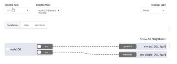
What is correct about the selected device shown in the exhibit?
Answer : C
The exhibit shows node100 (Generic System) selected, with links from that generic system to two fabric leaf switches (for example, a leaf participating in an ESI pair and another leaf node). In Apstra 5.1, a Generic System represents an endpoint that is not managed as a network device by Apstra (such as a server, appliance, or host), but it is still modeled so Apstra can apply interface intent (LAG vs single link), connectivity templates, and virtual network attachments.
Because the device is shown as a generic system connected on leaf-facing ports inside the fabric topology, this aligns with an internal generic system. Internal generic systems are used for servers or endpoints that reside ''inside'' the rack/fabric context and consume leaf switch ports as access-facing connections. This is the common representation for endpoints in EVPN-VXLAN data center designs, where the leaf switches provide the VLAN/VNI mapping and, if required, IRB gateway services within the tenant VRF (routing zone).
An external generic system is typically used for devices outside the fabric boundary---most commonly external routers, firewalls, or upstream networks attached at border leafs---where the intent is external connectivity rather than server access. The selected node is neither a peer switch nor an access switch (those are network infrastructure roles), and the UI explicitly labels it as a Generic System, confirming the correct classification as an internal generic system.
Question 5
You staged several changes to your Juniper Apstra blueprint but have not committed them. In this scenario, what is the effect of selecting Revert?
Answer : A
In Apstra 5.1, blueprint changes follow an intent workflow: you edit intent in Staged, then review the delta in Uncommitted, and finally Commit to activate those changes and create a new revision. If you have staged changes that are visible under Uncommitted but decide not to proceed, the Revert action is used to discard them. Selecting Revert clears the blueprint's uncommitted intent delta and returns the blueprint to the last committed state (the currently active intended design baseline). In practical terms, it removes all pending edits that were made since the last commit---whether those edits were physical (links/topology), virtual (routing zones, virtual networks), policies (security policies), or catalog-driven operations---so that none of those changes will be deployed.
Revert is not a ''single-step undo'' limited to only the most recent change; it is a discard of the staged/uncommitted change set. It also does not roll back device configurations on its own (that is handled by revision operations such as Time Voyager rollbacks and subsequent deployment actions). Finally, Revert does not require a commit to take effect; it is used specifically to avoid committing changes. This behavior helps maintain clean operational control in EVPN-VXLAN fabrics by ensuring only validated and intentional intent updates are promoted to the deployed network state.
Verified Juniper sources (URLs):
https://www.juniper.net/documentation/us/en/software/apstra4.2/apstra-user-guide/topics/task/blueprint-commit-revert.html
https://www.juniper.net/documentation/us/en/software/apstra6.1/apstra-user-guide/topics/task/time-voyager-rollback-blueprint-revision.html
Question 6
What is the purpose of a Juniper Apstra rack?
Answer : B
A Juniper Apstra rack is a physical entity that contains one or more network devices, such as leaf nodes, access switches, or generic systems. A rack is used to organize and manage the network devices in the Apstra software application. A rack has the following characteristics:
It stores information on how leaf nodes connect to generic devices. This is because a rack can include generic systems, which are devices that are not managed by Juniper Apstra, but are connected to the network. A generic system can be a server, a firewall, a load balancer, or any other device that has a network interface.A rack stores the information on how the leaf nodes, which are the devices that provide access to the end hosts, connect to the generic devices, such as the port number, the link speed, the LAG mode, and the roles1.
It has a rack type, which defines the type and number of leaf devices, access switches, and/or generic systems that are used in the rack. A rack type is a resource that is created in the data center design phase, and it does not specify the vendor or the model of the devices.A rack type can be predefined or custom-made, and it can be used to create multiple racks with the same structure and configuration2.
It has a rack build, which assigns the specific vendor and model of the devices to the rack. A rack build is created in the staged phase, and it uses the rack type as a template.A rack build can also assign the resources, such as the IP addresses, the ASNs, and the VNIs, to the devices in the rack3.
It has a rack deployment, which applies the network configuration and services to the devices in the rack. A rack deployment is performed in the active phase, and it uses the rack build as a reference.A rack deployment can also monitor the network performance and compliance of the devices in the rack4.
The following three statements are incorrect in this scenario:
It stores information on how pods connect to super spines. This is not true, because a rack does not store any information on the pod or the super spine level of the network. A pod is a cluster of leaf and spine devices that form a 3-stage Clos topology, and a super spine is a device that connects multiple pods in a 5-stage Clos topology.A rack only stores information on the leaf and the access level of the network1.
It stores IP address and ASN pool information. This is not true, because a rack does not store any information on the IP address and ASN pools. IP address and ASN pools are resources that are created in the data center design phase, and they contain a range of IP addresses and ASNs that can be assigned to the devices and the virtual networks.A rack only uses the IP address and ASN pools to assign the resources to the devices in the rack build2.
It stores device port data rates and vendor information. This is not true, because a rack does not store any information on the device port data rates and vendor information. The device port data rates and vendor information are specified in the rack build, which assigns the specific vendor and model of the devices to the rack.A rack only uses the rack build to apply the network configuration and services to the devices in the rack deployment3.
Racks (Staged)
Rack Types (Datacenter Design)
Rack Builds (Staged)
Racks (Active)
Question 7
Which statement is correct about an event log?
Answer : A
In Juniper Apstra 5.1, the Event Log is a centralized record used for auditing and operational visibility. It includes audit events (user/system actions) and anomaly-related alerts (events generated when Apstra detects abnormal conditions). In Apstra documentation, anomaly entries are explicitly treated as ''Alert'' records with high severity, meaning the Event Log is a valid place to review anomaly notifications and their associated details. Therefore, the statement that the Event Log stores alerts for anomalies is correct.
The other options do not match the Event Log function. Viewing a device's configuration is handled in device configuration and blueprint operational views, not as the primary purpose of the Event Log. Export behavior, where supported, is described for formats such as CSV rather than PDF, and exporting dashboards is a separate capability from event logging. Finally, while worker nodes are used to offload operational services (such as off-box agents and IBA components), the Event Log is a platform logging feature exposed through the controller UI/API rather than something described as ''running on the worker node'' as its defining trait.
Verified Juniper sources (URLs):
https://www.juniper.net/documentation/us/en/software/apstra5.1/apstra-user-guide/topics/topic-map/event-log.html
https://www.juniper.net/documentation/us/en/software/apstra5.0/apstra-user-guide/topics/topic-map/event-log.html
https://www.juniper.net/documentation/us/en/software/apstra5.1/apstra-user-guide/topics/topic-map/syslog-config.html